 Lifting Lug Design
This is the documentation page for the Lifting Lug Design module. You'll find here everything you need to understand how to use our application.
This module was created using the lug analysis from the Stress Analysis Manual created by Gene E. Maddux from Air Force Flight Dynamics Laboratory[ 1 ]. If you want to learn more about lug design according to this manual, visit the Lifting Lug Design article.
1. Types
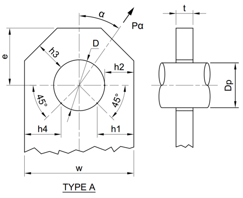
2. Drawing
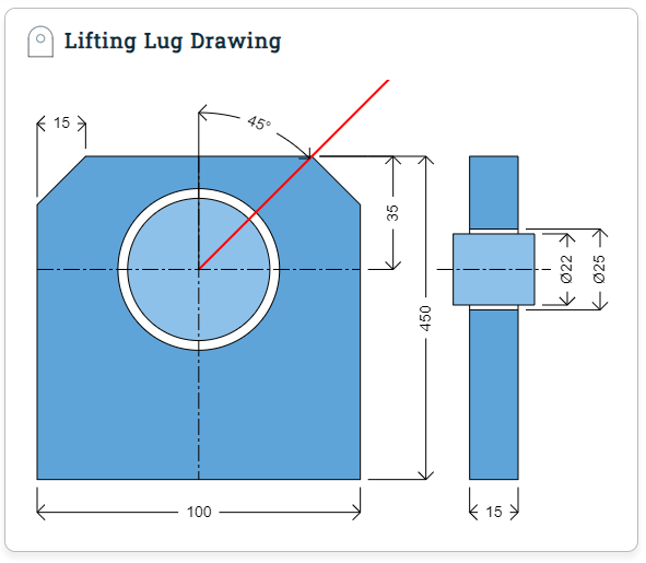
The drawings for the lifting lug types are generate dynamically and updated every time the USER change a dimension. After the button Run is clicked, the Results page will be shown and the drawing can no longer be changed (unless the USER click in the Back button).
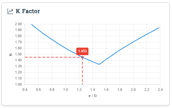
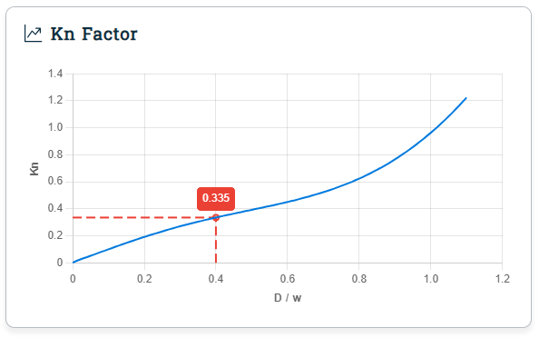
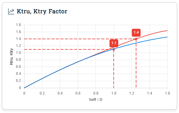
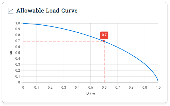
3. Charts
The charts (Fig. 3.1, 3.2, 3.3 and 3.4) will be show in the result page with the project data highlighted (red rectangle with white font). It'll also be in the Calculation Report.
4. Units
For now (version 1.0.0), only International Unit System[ 2 ] or just SI Units is accepted, but we're working to implement the Imperial Unit System[ 3 ] in the following versions, as it's still used by many countries (specially USA) and companies.
5. Fields
Below is a list of all the available fields in the Module.
5.1. Module
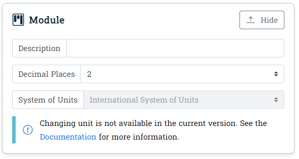
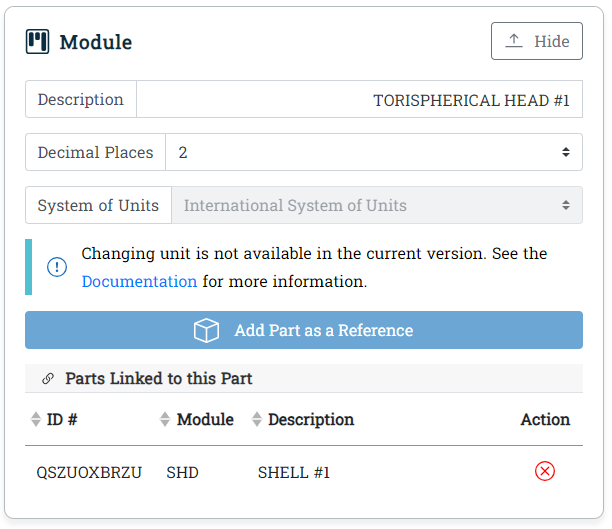
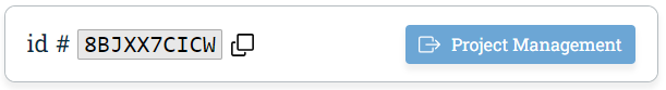
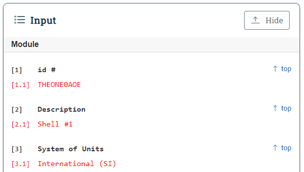
The module tab have two versions: one for a new part (see Fig. 5.1.1) and one for an existing part (see Fig. 5.1.2). The difference is that when a part is saved, an unique identifier (ID) will be generated for it and it can be linked to other parts and equipment. The ID is shown above the Module tab (see Fig. 5.1.3) and there's a button to Project Management module beside it.
Variable | Name | Unit | Type | Description |
|---|---|---|---|---|
| <none> | Description | <none> | Select | Short description of the part. For example: if designing a Bolted Flange to be connected at the upper part of the vessel, you can simply call if Upper Flange, if there's other flanges in there, you can be even more specific, calling if Upper Left Flange or Upper Gas Flange. Just remember that you'll use the description to identify the part (you can also use its id, but it's usually difficult to remember) |
| <none> | System of Units | <none> | Select | Unit system that will define the units used in all the variables in the calculation. The most known types are Imperial System and International System. Unfortunately we still don't support changing units and the International System will be used as a default. |
| <none> | Decimal Places | <none> | Select | Number of decimal places to be used in the calculations and results. User can choose between 1 to 4 decimal places (also known as precision). |
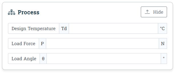
5.2. Process
Variable | Name | Unit | Type | Required | Description |
|---|---|---|---|---|---|
| Td | Design Temperature | °C, °F | Field | Yes | Maximum expected temperature in lug. Tip: you can use the same value used for vessel part where it'll be welded. |
| P | Load Force | N, lbf | Field | Yes | Maximum expected load force acting in the lug. |
| θ | Load Angle | ° | Field | Yes | Angle of the applied load force (P). Minimum 0° and maximum 90°. Can't be negative. |
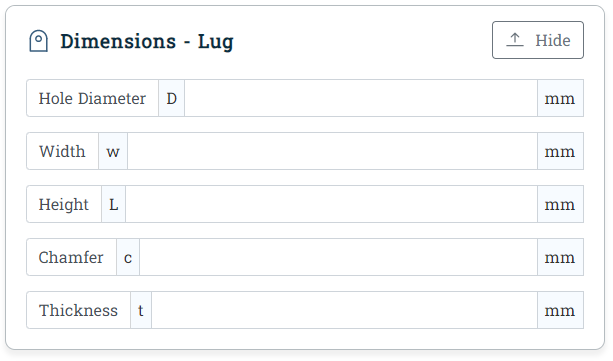
5.3. Dimensions
5.3.1. Single Lug
Variable | Name | Unit | Type | Required | Description |
|---|---|---|---|---|---|
| D | Hole Diameter | mm, in | Field | Yes | xxx |
| W | Width | mm, in | Field | Yes | xxx |
| L | Height | mm, in | Field | Yes | xxx |
| c | Chamfer | mm, in | Field | Yes | xxx |
| t | Plate Thickness | mm, in | Field | Yes | xxx |
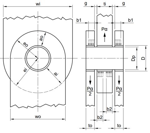
5.3.2. Lug Joint
5.4. Material
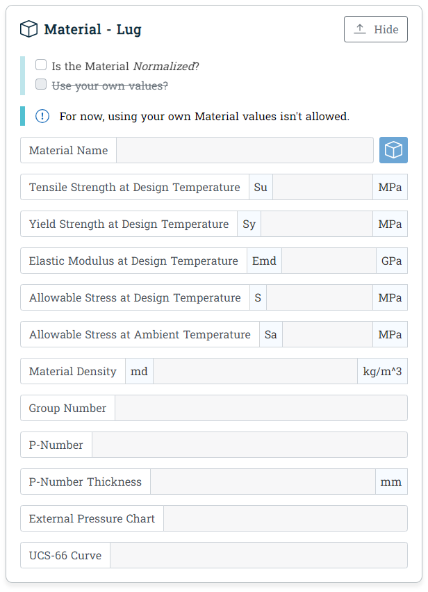
Lifting Lug Design module have three material tab, one for each part: Lug, Pin and Bushing. All material tab have the same fields so the description in this section will apply for them all.
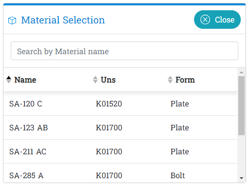
To select material click in the white box icon beside the Material Name field, a modal window (see Fig. 4.4.2.) will appear with a list of available materials. Click in the material name to select it. You can use the search field to speed the process. It'll filter all columns.
Variable | Name | Unit | Type | Required | Description |
|---|---|---|---|---|---|
| <none> | Is the Material Normalized? | <none> | Checkbox | No | xxx |
| <none> | Use your own values? | <none> | Checkbox | No | xxx |
| <none> | Material Name | <none> | Select | Yes | xxx |
| Su | Tensile Strength at Design Temperature | MPa, psi | Field | Yes | xxx |
| Sy | Yield Strength at Design Temperature | MPa, psi | Field | Yes | xxx |
| Emd | Elastic Modulus at Design Temperature | GPa, kpsi | Field | Yes | xxx |
| S | Allowable Stress at Design Temperature | MPa, psi | Field | Yes | xxx |
| Sa | Allowable Stress at Ambient Temperature | MPa, psi | Field | Yes | xxx |
| md | Material Density | kg/m^3, lbf/in^3 | Field | Yes | xxx |
| <none> | Group Number | <none> | Field | Yes | xxx |
| <none> | P-Number | <none> | Field | Yes | xxx |
| <none> | P-Number Thickness | mm, in | Field | Yes | xxx |
| <none> | External Pressure Chart | <none> | Field | Yes | xxx |
| <none> | UCS-66 Curve | <none> | Field | Yes | xxx |
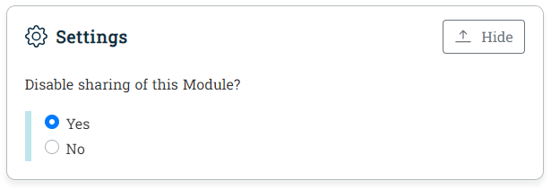
5.5. Settings
Variable | Name | Unit | Type | Required | Description |
|---|---|---|---|---|---|
| <none> | Disable sharing of this Part? | <none> | Checkbox | Yes | If set to "Yes", other USERs will not be able to add this Part to their Equipment. Part owner can still add it to his own Equipment. See Sharing section for more information. Default: Yes. |
6. Messages
The Module will show messages in the results pages when needed.
6.1. Warnings
6.2. Info
7. Sharing
The sharing option is something that we thought would be useful because engineers works as a team and usually share their projects with another engineers or customers, either to review or for approval.
Nowadays working side by side (physically) with other engineers is becoming something from the past. Hybrid and Remote position are becoming common in many companies. So no more printing the project and let in the co-work table to be checked. You either send the PDF (or software file) by e-mail or save it in the company drive.
Our approach is a little bit better. We let the USER choose which USERs can access the project, equipment and part and what kind of permission they will have. You can let some USERs change anything in a Part or let they only see it (input and output).
To share a project, equipment or part you must be its owner. You can be the owner by either creating the project, equipment or part or if the current owner delegates it to you. Also the option Disable sharing of this Part? in the Settings tab must be set to No (see Fig. 4.5.1), in case of Part and if it's a Project or Equipment, the sharing button in the PJM module must be set to enable (see more about it in the Project Management documentation).
Currently there are two types of sharing status:
- Full Access: this type of access let the USER make changes to the Project, Equipment and Part but can't delete it (only its owner can do that)
- View Access: USER with this type of access can't make changes, can only see the input and output data.
8. Limitations
The version 1.0.0 comes with some limitations which are listed below:
-
This version can't be used to calculate the following situations:
- xxx
9. Results
The results page is composed by 5 important parts: Summary, Input, Output, Bottom Menu, Summary and drawing (there's no section for the drawing because it's just the same as show in the input page).
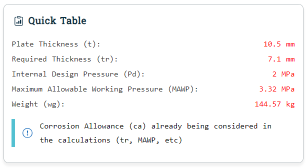
9.1. Summary
The Summary (see Fig. 9.1.1.) shows the most important information from the results. It also shows if there's some error in the calculation (it'll be shown in red).
In the future version we'll let the USER select which information want to see in it.
9.2. Input
The Input tab (see Fig. 9.2.1.) in the results page shows all the information from the input page. It can be used to check all the data inserted by the USER and by our system. The input will also be shown in the Calculation Report.
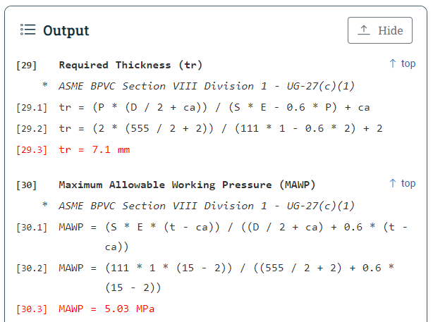
9.3. Output
9.4. Bottom Menu
At the bottom of the page you'll find three buttons (see Fig. 9.4.1.):
- Back: will bring the USER back to the Input page
- Save: will save the Part and the USER will be able to access it using the direct link shown in the browser or through the Project Management module
- Report: will generate and download the Calculation Report

9.5. Summary
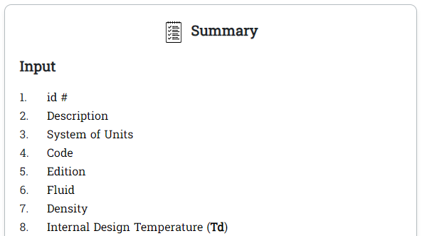
To help USER easily check the equations and input data we created a summary which is show at the right side of the page (see Fig. 9.5.1.). It's composed by hyperlinks and if clicked the part where the item is located will be show. The list is divided in Input and Output to facilitate the identification.
10. Testing
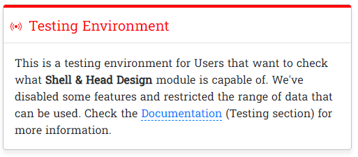
If you access the Lifting Lug Design module without being logged, you'll see a warning message as shown in the Fig. 10.1. stating that you're entering into a testing environment, which basically means that you'll not be able to use it in a real case, as some features are disabled and the data range that can be use is limited.
If you need to use the it beyond its testing limitation, contact us through Contact page and we'll see what can we do for you. We could, for example, give you a 1 day free trial or a guided testing with us.
10.1. Limitations
There are two types of limitation in the Testing Environment: features disabled and data range restriction.
109.1.1. Features Disabled
Feature | Limitation |
|---|---|
| System of Units | For now (version 1.0.0) the System of Units is disabled for every case, not only for testing environment. We're still checking the real need to make Imperial Units available. |
| Fluid | Only the fluid ASTM — Ref Motor Fuel C (50% Aromatic) are available for testing. Before you ask, we choose it at random. As the fluid isn't required by the calculation, we believe that disabling its selection won't affect the USER experience. |
| Type | Two types are available for testing: Cylindrical Shell and Torispherical Head. We've choose it because it's the most used types. |
| Material Name | Only the material SA-512 A are available for testing now but we're evaluating the possibility to let the USER choose between 3 materials, to test the Search Material feature. |
| What Test specification should be used? | Only the Hydrostatic Test (UG-99(b)) is available for testing. As it's quite simple calculation, it shouldn't affect the USER experience while testing the Module. |
| Disable sharing of this Part? | Sharing didn't affect the calculation and isn't shown in the Calculation Report, so disabling it should't affect USER experience. |
| Include Operating Hydrostatic Pressure? | Hydrostatic pressure can sometimes be neglected in the calculations because it's usually very small, so disabling it shouldn't affect USER experience. If you want to calculate it by yourself, just check this article Hydrostatic Pressure on Head and Shell. |
| Include Test Hydrostatic Pressure? | Same as the option Include Operating Hydrostatic Pressure? but in this case we're using he test pressure, which are higher than the operating pressure but, even so, it's value continues to be very small. |
10.1.2. Data Range Restriction
Variable | Description | Limitation |
|---|---|---|
| <none> | Decimal Places | 1 to 3 |
| To | Operating Internal Temperature | 0 to 120°C |
| Po | Operating Internal Pressure | 0.5 to 2.0 MPa |
| Td | Design Internal Temperature | 0 to 120°C |
| Pd | Design Internal Pressure | 0.5 to 2.0 MPa |
| Toe | Operating External Temperature | 0 to 120°C |
| Poe | Operating External Pressure | 0.5 to 2.0 MPa |
| Tde | Design External Temperature | 0 to 120°C |
| Pde | Design External Pressure | 0.5 to 2.0 MPa |
| <none> | Type | Cylindrical Shell or Torispherical Head |
| D | Inside Diameter | 1 to 600 mm |
| sl | Shell Length | 1 to 1200 mm |
| t | Plate Thickness | 1 to 12 mm |
| ca | Corrosion Allowance | 0 to 5 mm |
| E | Joint Efficiency | 0.45 to 1.00 |
| L | Inside Crown Radius | 1 to 600 mm |
| r | Inside Knuckle Radius | 1 to 150 mm |
| s | Straight Flange Length | 0 to 30 mm |
| mdmt | Minimum Design Metal Temperature | 0 to 60°C |
10.2. Access Protection
The public API used in the testing environment is different from the API used in the production environment. So, even if someone tries to direct access the API with values outside the data range, the API will return an error.
11. Linking Parts
The calculation modules that we've in the ΣCalc or, more specifically, in the MarsCalc package, works independently from each other. It means that, if you are designing a spherical head to be attached in a conical shell, one part will not "know" about the other. The only exception are the modules that require the USER to load data from other modules. It's the case for Opening Reinforcement Design (ORD) and Saddle Support Design (SSD).
To let the USER specify which parts are connected, we created the reference list. Let say, for example, that you have a torispherical head connected to a cylindrical shell. If you go to the Equipment tab in the Project Management module you'll see that the equipment have many parts, including the head and shell specified above but, you can't know how they are connected. If you add the cylindrical shell as a reference to the torispherical head, you'll know that it's connected.
The problem now is: what if the cylindrical shell have two heads, how can you know which one is in the top and which is in the bottom? Unfortunately we don't have a way to specify that, we're planning to let USER to assembly the pressure vessel just like PVElite does (using 2D drawings and nodes to connect the parts) but it isn't our top priority (it is listed in the Pool of Ideas with the ID # 9FF565B5)
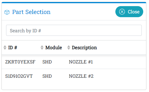
Okay, lets go to the how to part. To add a part as a reference, first make sure that both parts are saved (exist and have and ID), then click in the Add part as a Reference (see Fig. 4.1.2) button. A modal (see Fig. 11.1) will be shown with the list of all parts created by the USER. If there are too many parts and you already know the ID of the part that you which to add, just type it in the search field to filter the list. To finish, just click in the part that you want to add and the modal will close and it'll appear in the Parts Linked to this Part table in the Module tab.
One important thing that you must understand: linked parts have no effect in the calculation. It serves only as a reference. So if you add a stainless steel part to a carbon steel, the application won't show any warning.
12. Creating the Charts from the Manual
Unfortunately the manual don't give the equations and/or the points for the charts (figures 9-2, 9-3 and 9-4 from the manual) shown in it, we also couldn't find it online, so we had to find a way to get it manually and we'll show you bellow the step-by-step process that we used.
- Use the Snipping Tool to capture the screenshot of the chart you want to create.
- Import the screenshot to AutoCAD using the Attach command. Don't worry about the scale now as you'll set it in the next step.
- Use Scale command to scale the image according to the dimensions shown in the chart. For example: the Figure 9-2 from the manual have the horizontal dimension of 2 (2.4 - 0.4), so you'll have to set the distance from the first point (0.4) to the last point (2.4) as 2.
- Use the Move command to move the (0,0) coordinate of the chart to the (0,0) coordinate of the AutoCAD. Do that by typing move in the console, then hit enter (keyboard), select the first point, then type 0,0 in the console and hit enter.
- Now you'll have to create the points which will be used to generate the chart. Use the Point or Donut command for that. Place as much points as needed (more points means better precision, if you do it right, of course) along the chart lines.
- Use the DataExtraction command to extract the location (x, y) of the points to an Excel file.
13. Calculation Report
Calculation report can be generated and downloaded by clicking on the Report button located in the bottom menu, which is only visible in the results page. The file name will be the part ID.
Fig. 13.1. shows the information contained in the first page of the report. Company name and logo can be set in the Dashboard. All the other information are automatically generated.
 Fig. 13.1. - Calculation Report second page
The second page will show the part description (information given by the USER in the Module tab), part id (automatically generated), drawing (same as shown in the input page), input and output (equations).
 Fig. 13.2. - Calculation Report first page
Changelog (doc)
If you want to receive an e-mail notification every time an article or documentation is updated, just sign up and click in the Notify Me button at the bottom of the page (only visible for logged USERs).