 Lifting Lug Design - Air Force Method
The intention of this article is to explain to the USER, in a simple way, how to design lifting lugs according to what is called the Air Force Method. Such method is described in the section 9 of the Stress Analysis Manual[ 1 ] authored by Gene E. Maddux, Leon A. Vorts, F. Joseph Giessler and Terence Moritz and published in 1969 by Technology Incorporated Dayton as a Technical Report sponsored by USAF Flight Dynamics Laboratory. It was unclassified in 1971 and now everyone can have access to it for free.
Although it's a quite old document, it's still a reliable source of information for engineers and can be used in real world projects. If the USER don't want to use this method, there are other options:
- ASME BTH-1: Design of Below-the-Hook Lifting Devices[ 2 ]
- AISC 360: Specification for Structural Steel Buildings[ 3 ]
Both are updated regularly, ASME is easier to use and understand but, as any other code from ASME it's paid (and isn't cheap), AISC 360 can be downloaded for free at their website (link in the References section).
1. Before Start
Although this is a reliable method to design lifting lugs, I wouldn't advice you to use it in critical projects (for example: equipment weighting more than 1 ton or lifting something 20 meters from the ground), in this case, use ASME BTH-1 as it's way more complete. Just for comparison, the Stress Analysis Manual have only 50 pages dedicated to lug analysis while ASME BTH-1 have 68 with two column text.
It's not the intention of this article to explain to the USER where the lugs must be welded, how many lugs must be used, cable dimensions, lifting angles and any other thing that isn't the lug, we did this to keep this article simple and, in the future, we may create other articles addressing these topics.
You'll need the following project data to get started:
- Load force - it's basically the equipment weight but, you must pay attention to the percentage of the weight that will be applied to the lug being designed. If you only have one lug (which isn't common) then, it'll hold 100% of the equipment weight. If it have two lugs then, each lug will hold 50% and so on.
- Load angle - it's the angle of the lifting cable attached to the lug. Fig. 1.1. shows some examples: (a) is a 45° angle, (b) is a 60° angle and (c) is a 90° angle.
- Lug material - it's a good practice that the lug material be the same as the equipment it'll be welded to avoid welding and corrosion problems.
- Lug maximum width - although lifting lugs are usually quite small compared to the equipment it's fixed, it's a good practice to know the maximum width it can have in order to avoid assembly problems.
- Single lug or joint - this is an important information that will define the steps in the calculation. A joint is a combination of three lugs, two welded to the equipment side by side with a gap between them and, in the middle will be another lug. The lugs are connected by a pin. It isn't a common configuration but the USER must know that it exist.
- Cable or hook dimensions - this information will be used to define the lug hole or the pin diameter. If cable will be used them, you'll only need its diameter. If hook them, you'll need to check if it can pass through the hole.
You can get the information from items (2), (5) and (6) with the team responsible for the rigging.
 Fig. 1.1 - Lifting cable angles
2. Getting Started
Okay, now that you have all the project information needed, start by drawing the lug. You can use 2D (AutoCAD or similar) or 3D (SolidWorks or similar) CAD software to do that (to be honest, you can even use pen and paper but, for the sake of documentation, I highly advise to use a CAD software, because you'll have the file saved for later access).
Fig. 2.1. shows some types of lifting lugs. The first two ((a) and (b)) is usually used when you have an axial loading and the last two ((c) and (d)) when you have oblique or transverse loading.
 Fig. 2.1 - Lifting lug types
The Air Force Method approach is "guess the dimensions, calculate, if fail, change dimensions, calculate again, keep doing until succeed". So draw the lug using the information that you have and guess what you don't have, but try to be realistic (for example: don't use very small thickness or very big pin hole).
 Fig. 2.2 - Lug Dimensions
3. Dimensions
3.1. Uniform Axial Load
 Fig. 3.1 - Lug Dimensions
The Fig. 2.2 above shows the dimensions needed to draw a lug under uniform axial load. The variables description is as follow:
- t - lug thickness
- W - lug width
- WT - lug tang width
- L - distance from base to pin hole
- a - distance from the edge of the hole to the edge of the lug
- D - hole diameter for the pin
- DP - pin diameter
- e - edge distance
- P - load
Regarding the lug thickness, variable t, use standard plate thickness, you can easily find tables with this information in the internet or contacting your local Vendor.
Make the distance between the base and the pin hole, variable L, as small as possible to avoid high bending stress in the base when subject to oblique or transverse load.
3. Charts
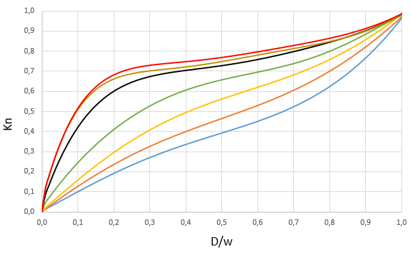
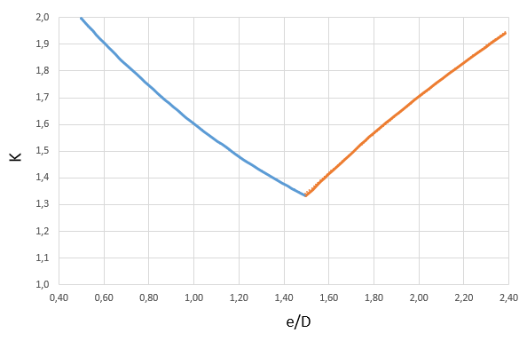
There are a lot of charts in the manual (23 to be more precise) which was created using empirical data, two of this charts are shown bellow (Fig. 3.1 and 3.2). We'll not put all the charts in here because it would make the page very "heavy" to load, so we advice the USER to check it using the manual as it's free to download.
 Fig. 3.1 - Net Tension Stress Coefficient chart
 Fig. 3.2 - Allowable Uniform Axial Load Coefficient chart
4. Examples
To avoid adding too much information in this page, making it heavy to load, we decided to not include any examples of calculation, we also did that because the manual have examples inside it which are easy to understand.
Changelog (doc)
If you want to receive an e-mail notification every time an article or documentation is updated, just sign up and click in the Notify Me button at the bottom of the page (only visible for logged USERs).