 Bolted Flange Volume and Weight
Unfortunately ASME BPVC Section VIII don't give an equation or a step-by-step procedure to calculate bolted flange weight (same happens with torispherical head[ 1 ]), pressure vessel design softwares (PVElite, CodeCompress, AutoPipe) also don't show the calculation, only the results. In the end, it makes sense as it's something that can easily be found using CAD softwares (AutoCAD, Inventor, SolidWorks) and it would only add a lot of lines to a report that already have many pages.
We'll not show the calculation in our reports but we'll explain how to find the weight in this article and will add a referente (see Figure 0.1. below) in the report that our application generates, so the designer can check how we came to the result.
 Fig. 0.1. - Link to this article shown in the Calculation Report
1. Types of Bolted Flanges
Basically there are only two types of bolted flanges: ring types (Fig. 1.1.(1)) and flange with hub (Fig. 1.1.(2)). These two types are present in the ASME BPVC Section VIII Division 1 Appendix 2[ 2 ]
 Fig. 1.1. - Types of bolted flanges
2. Method
- Define the sections
- Calculate the areas
- Find the areas centroid
- Calculate each section volume
- Sum all volumes
- Multiply the volume by the material density
3. Section Definition
There are many ways to define the sections of a bolted flange to calculate its volume and weight. The Figure 3.1. shows the one that we found the most efficient. It's basically 3 rectangles and 1 triangle.
 Fig. 3.1. - Section definition of a bolted flange with hub
Sections dimensions:
Item 1
- Height (1a): flange face thickness (faceT)
- Width (1b): flange face outside diameter (faceOD) - flange face inside diameter (faceID)
Item 2
- Height (2a): flange thickness (t)
- Width (2b): flange outside diameter (A) - flange inside diameter (B)
Item 3
- Height (3a): hub length (h)
- Width (3b): hub small end thickness (g0)
Item 4
- Height (4a): hub length (h)
- Width (4b): hub back of flange thickness (g1) - hub small end thickness (g0)
4. Area Centroid
The centroid of an area can be thought of as the geometric center of that area. If you have a simple shape as a square, triangle, circle or rectangle, it'll be quite easy and won't need any calculation but, if you have a complex shape, you'll have to divide it in simple shapes and use the combined shape method to find the centroid (you'll find the method in the item 4.1. below)
4.1. Centroid of a Combined Shape
 Fig. 4.1.1. - Bolted Flange with Hub Sections
Consider the Figure 4.1.1. shown above which is composed by three shapes: square (item 3), rectangle (item 2) and triangle (item 1). The origin (0,0) will be set at the bottom left corner of the square. Values above and to the right of the origin will be positive. The equations (1) and (2) will be used to find the centroid of the composed shapes in the x and y direction.
$$\begin{align}\overline{X}= {\dfrac{\Sigma (x_i \cdot A_i)}{\Sigma A_i}}\tag{1}\end{align}$$ $$\begin{align}\overline{Y}= {\dfrac{\Sigma (y_i \cdot A_i)}{\Sigma A_i}}\tag{2}\end{align}$$Steps to be followed:
- Find the area of each shape
- Find its centroid related to the origin
- Multiply the shape centroid in the x direction by its area
- Multiply the shape centroid in the y direction by its area
- Sum the values found in the step 3
- Sum the values found in the step 4
- Sum the values of all areas
- Divide the value from step 5 by the value from step 7 to find the composed shape centroid in the x direction
- Divide the value from step 6 by the value from step 7 to find the composed shape centroid in the y direction
It's easier if you create a table to put all the values as shown in Table 4.1.1.
| Item | Area mm^2 | x mm | y mm | x̄ mm | ȳ mm | x̄A mm^3 | ȳA mm^3 |
|---|---|---|---|---|---|---|---|
| 1 | 8.4 | 4 | 4.2 | 7.67 | 5.4 | 64.428 | 45.36 |
| 2 | 10.5 | 3 | 3.5 | 6.5 | 3.25 | 68.25 | 34.125 |
| 3 | 25 | 5 | 5 | 2.5 | 2.5 | 62.5 | 62.5 |
| Total | 43.9 | 195.178 | 141.985 |
Results:
$$\begin{align}\overline{X}= {\dfrac{\Sigma (x_i \cdot A_i)}{\Sigma A_i}}={\dfrac{195.178}{43.9}}={4.44 \; mm}\tag{3}\end{align}$$ $$\begin{align}\overline{Y}= {\dfrac{\Sigma (y_i \cdot A_i)}{\Sigma A_i}}={\dfrac{141.985}{43.9}}={3.23 \; mm}\tag{4}\end{align}$$4.2. Centroid of a Bolted Flange with Hub
 Fig. 4.2.1. - Centroid position of bolted flange sections
| Item | Area mm^2 | x mm | y mm | x̄ mm | ȳ mm | x̄A mm^3 | ȳA mm^3 |
|---|---|---|---|---|---|---|---|
| 1 | 1b * 1a | 1b | 1a | 1b / 2 + B | 3a + 2a + 1a / 2 | (1b * 1a) * (1b / 2 + B) | (1b * 1a) * (3a + 2a + 1a / 2) |
| 2 | 2b * 2a | 2b | 2a | 2b / 2 + B | 3a + 2a / 2 | (2b * 2a) * (2b / 2 + B) | (2b * 2a) * (3a + 2a / 2) |
| 3 | (3b * 3a) / 2 | 3b | 3a | 3b / 2 + B | 3a / 2 | ((3b * 3a) / 2) * (3b / 2 + B) | ((3b * 3a) / 2) * (3a / 2) |
| 4 | 4b * 4a | 4b | 4a | 4b / 3 + B | 2 / 3 * 4a | (4b * 4a) * (4b / 3 + B) | (4b * 4a) * (2 / 3 * 4a) |
5. Volume
Finding the volume of a shape around an axis is quite simple after you have found its area and centroid. Figure 5.1. show the composed shape with two dimensions: distance from the y and x axis to the centroid. To find the shape volume considering that it'll be revolved around the y axis, use Equation (5), if it's rotated around x axis, use Equation (6).
 Fig. 5.1. - Composed shape centroid position
Applying the values from Table 4.1.1. in the Equations (5) and (6) we have the results shown in the Equations (7) and (8) below:
$$\begin{align}V_y= {2 \cdot \pi \cdot 43.9 \cdot 4.44 = 1224.69 \; mm^3}\tag{7}\end{align}$$ $$\begin{align}V_x= {2 \cdot \pi \cdot 43.9 \cdot 3.23 = 890.94 \; mm^3}\tag{8}\end{align}$$We got almost the same value as SolidWorks 2020 (see Figure 5.2. below). The difference happened because we truncated the values in the Table 4.1.1. to 2 decimal places. If you calculate the values with more decimal places, you'll get the exact same value as SolidWorks.
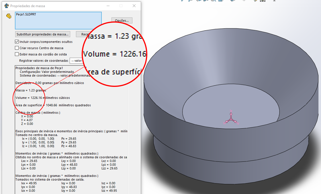 Fig. 5.2. - Volume calculated by SolidWorks 2020
6. Weight
The weight of the flange will depend on the material density (for those that have a valid Kezar Engineering subscription, we have the ASME Material Database module) and, of course, its volume.
$$\begin{align}fw= {V \cdot density}\tag{9}\end{align}$$Using the density of stainless steel (8000 kg/m^3) and the volume found in the Equation (7) in the Equation (10) we find the shape weight:
$$\begin{align}fw= {1224.69 \cdot 10^{-9} \cdot 8000 = 1.0 \; kg}\tag{10}\end{align}$$